MFM13A Install Guide
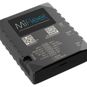
MFM13A Vehicle Tracker
Installation Guide
What's Included
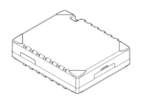
MFM13A Device
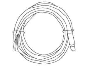
12 Pin Power Harness
Special Note Before Install
3 Wire Install
1. Locate your vehicle’s unswitched 3-wire:
2. 12V/24V power line
3. Ignition sense (greater than 9V),
4. Ground line
Verify that the ignition sense exceeds 9 volts when on.
*For best results, it is strongly recommended that the device connection be on its own circuit. If possible, connect the power input directly to the vehicle battery and protect the circuit with an InLine fuse. If you must connect through the fuse box, use standard commercial wiring practices to create a permanent installation rather than using press-in fuse clips or other temporary measures.
1. Connect black wire to vehicle’s ground line.
*Must be connected to chassis ground.
2.Connect red wire to vehicle’s primary power source.
*Must be connected to a constant (unswitched) +12 VDC or +24 VDC supply. The preferred method is to connect directly to the vehicle battery terminal line.
3.Connect yellow wire to vehicle’s ignition line.
*The ignition line must be connected to the vehicle ignition or another appropriate key operated line, such as ACCESSORY, ensuring that power to the ignition wire is available only when the vehicle ignition is on.
Wire Connection Diagram
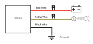
*Failure to connect these lines as described may result in discharge of the vehicle battery.
*Device and battery location may differ depending on vehicle model.
4. Locate an installation location for placement of the MiFleet hardware.
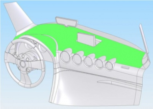
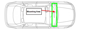
For large commercial vehicles and trucks we recommend mounting the device to the dashboard or glovebox as close to the window as possible. For a smaller compact vehicle we recommend mounting the device behind the dashboard (interior front plastic panel) as close to the window as possible.
The DEVICE STICKER SIDE MUST FACE THE SKY (the label shows “Mount This Side Up”) . Place the tracking device in line of sight. Do not place under metal, or adhere to the sub-frame chassis; this will cause interference.
A good example of placement is displayed in a picture below
(area colored green).
*To prevent the unit from moving or falling it is recommended to use a zip-tie to securely fasten the device to the vehicle sub frame. This is important to get accurate acceleration-based events.
5. Allow the Vehicle to run for a minimum of 15 minutes. This way, the data can transfer to the MiFleet Portal.
Green LED light will blink every second for normal mode. If LED light is solid, the GNSS signal is not received.
If there is no LED light there is no connection, please contact MiFleet support at 1.866.643.5338 opt 2.

