MF2830 Install Guide
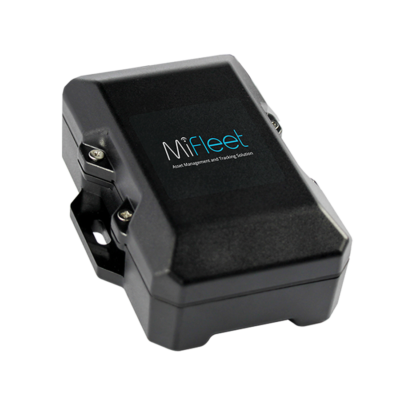
MF2830
Installation Guide
What's Included
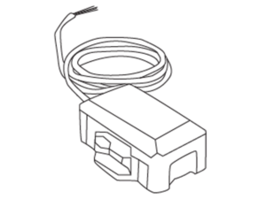
MF2830 Device
Mounting Screws
Install Type Quick Links
3 Wire Install
1. Locate your vehicle’s unswitched 3-wire:
1) 12V/24V power line
2) Ignition sense (greater than 9V),
3) Ground line
Verify that the ignition sense exceeds 9 volts when on.
*For best results, it is strongly recommended that the device connection be on its own circuit. If possible, connect the power input directly to the vehicle battery and protect the circuit with an InLine fuse. If you must connect through the fuse box, use standard commercial wiring practices to create a permanent installation rather than using press-in fuse clips or other temporary measures.
2. Connect black wire to vehicle’s ground line.
*Must be connected to chassis ground.
3. Connect red wire to vehicle’s primary power source.
*Must be connected to a constant (unswitched) +12 VDC or +24 VDC supply. The preferred method is to connect directly to the vehicle battery terminal line.
4. Connect white wire to vehicle’s ignition line.
*The ignition line must be connected to the vehicle ignition or another appropriate key operated line, such as ACCESSORY, ensuring that power to the ignition wire is available only when the vehicle ignition is on.
Wire Connection Diagram
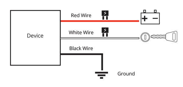
* Failure to connect these lines as described may result in discharge of the vehicle battery.
5. Place Device on surface in vehicle ensuring that top of device
(MiFleet logo side) faces the sky.
6. Allow the Vehicle to run for a minimum of 15 minutes. This way, the data can transfer to the MiFleet Portal.
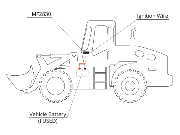
* Device and battery location may differ depending on vehicle model
Device can be used for a certain amount of days without the need to be wired for charging (see battery usage below).
1 message a day = 3-4 months of battery life
4 messages a day = 1 month of battery life
*Estimated battery life
Wired Trailer Install
1. Tracker must have a direct line of sight to the sky.
2. Try to avoid installation location with direct water kick up from tires as this will exceed the IP ratings per device specifications.
3. On many trailers, the AUX pin from the main plug or electrical panel supplies power typically the same as the ignition. You can also potentially use trailer lights, but make sure there is minimum of 1A that can be sourced to allow backup battery to charge while the trailer is connected to the vehicle.
4. Main plug should also contain valid 12V @ 1A max constant power and ground. Consult your trailer manufacturer or dealer if needed to confirm.
Wire Connection Diagram
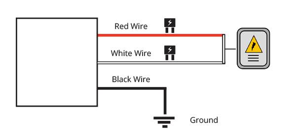
5. Chassis ground - Connect to MF2830 Black Wire, typically this is a white connection on the trailer harness.
6. Constant 12V power – Connect to Red and White Wire on the MF2830, this should be constant 12V power while the trailer is connected to the vehicle.
7. Refer to trailer install image (above) with red wire + white wire tied together going to electrical box.
HVAT Install
1. Locate your vehicle’s unswitched 3-wire:
1) 12V/24V power line
2) Ignition sense (greater than 9V)
3) Ground line
Verify that the ignition sense exceeds 9 volts when on.
*For best results, it is strongly recommended that the device connection be on its own circuit. If possible, connect the power input directly to the vehicle battery and protect the circuit with an InLine fuse. If you must connect through the fuse box, use standard commercial wiring practices to create a permanent installation rather than using press-in fuse clips or other temporary measures.
2. Place device on surface in vehicle ensuring that top of device (MiFleet logo side) faces the sky.
3. Allow vehicle to run for 10 minutes to allow for data to register on MiFleet portal.
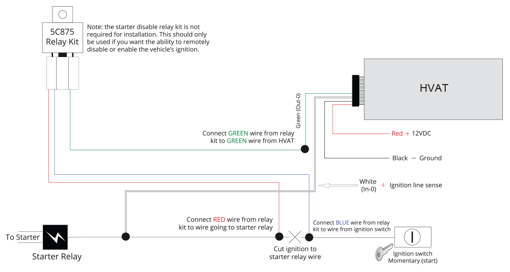
Follow Diagram Below For Proper Wiring Instructions.
HVAT Wired Trailer Install
1. Tracker must have a direct line of sight to the sky.
2. Try to avoid installation location with direct water kick up from tires as this will exceed the IP ratings per device specifications.
3. On many trailers, the AUX pin from the main plug or electrical panel supplies power typically the same as the ignition. You can also potentially use trailer lights, but make sure there is minimum of 1A that can be sourced to allow backup battery to charge while the trailer is connected to the vehicle.
4. Main plug should also contain valid 12V @ 1A max constant power and ground. Consult your trailer manufacturer or dealer if needed to confirm.
Wire Connection Diagram

5. Chassis ground - Connect to MF2830 Black Wire, typically this is a white connection on the trailer harness.
6. Constant 12V power – Connect to Red and White Wire on the MF2830, this should be constant 12V power while the trailer is connected to the vehicle.
7. Refer to trailer install image (above) with red wire + white wire tied together going to electrical box.


