MF4315 Install Guide
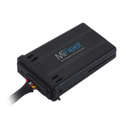
MF4315
Installation Guide
What's Included

MF4315 Device
3 Wire Install
1. Locate your vehicle’s unswitched 3-wire:
1) 12V/24V power line
2) Ignition sense (greater than 9V),
3) Ground line
Verify that the ignition sense exceeds 9 volts when on.
*For best results, it is strongly recommended that the device connection be on its own circuit. If possible, connect the power input directly to the vehicle battery and protect the circuit with an InLine fuse. If you must connect through the fuse box, use standard commercial wiring practices to create a permanent installation rather than using press-in fuse clips or other temporary measures.
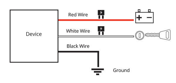
2. Connect black wire to vehicle’s ground line.
*Must be connected to chassis ground.
3. Connect red wire to vehicle’s primary power source.
*Must be connected to a constant (unswitched) +12 VDC or +24 VDC supply. The preferred method is to connect directly to the vehicle battery terminal line.
4. Connect white wire to vehicle’s ignition line.
*The ignition line must be connected to the vehicle ignition or another appropriate key operated line, such as ACCESSORY, ensuring that power to the ignition wire is available only when the vehicle ignition is on.
Wire Connection Diagram
* Failure to connect these lines as described may result in discharge of the vehicle battery.
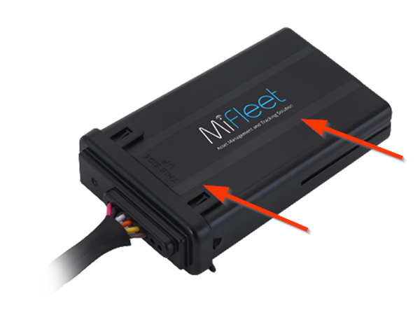
5. Place Device on surface in vehicle ensuring that top of device
(MiFleet logo side) faces the sky. It will also say - "This Side Up"
6. Allow the Vehicle to run for a minimum of 15 minutes. This way, the data can transfer to the MiFleet Portal.
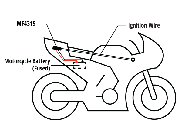
* Do not install under a metal surface. If possible install under plastic or other material, e.g. under the plastics of various fairings or rear seat.
Device and battery location may differ depending on vehicle model .
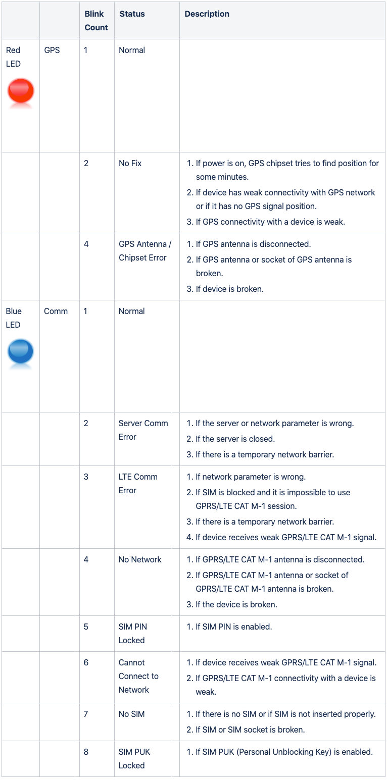
Status LEDs
